2.2.1 Calculation of Weight Stresses
- Meena Rezkallah, P.Eng.
- May 21, 2020
- 2 min read
Updated: Dec 20, 2020
Stresses due to weight loads acting on a supported pipe can be estimated through the use of beam theory. The simplest method of estimating pipe stresses due to weight is to first consider the pipe as being a continuous run, with supports located at constant intervals (this is a somewhat accurate model of piping traveling horizontally, mounted on racks, and with a minimum of in-line components):
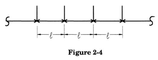
Elementary beam theory can be used to determine stresses in a member due to loading on that member. Normally the member considered is one-dimensional, homogenous with respect to cross-sectional and material parameters, and restrained in a number of degrees-of-freedom at one or both ends. This model can only be used if the effects examined are limited to two adjacent support points and the straight run of pipe between those support points. The question is what beam stress equation should be used?
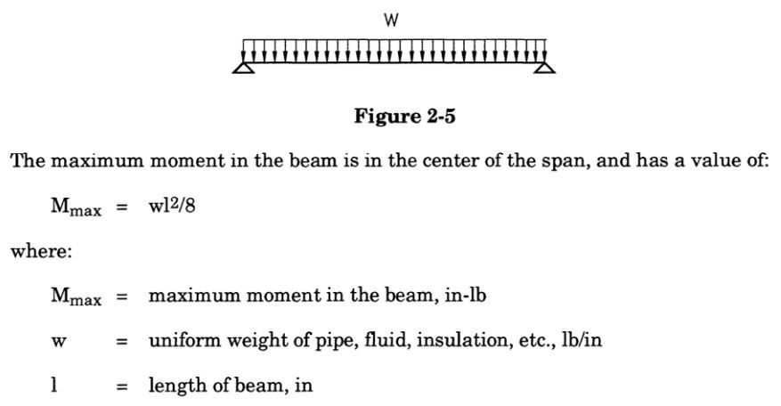
Beam theory states that if both support points are pinned (free to rotate):
If both ends are fixed, or rigid (restrained against rotation):
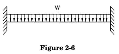
The maximum moment is at the ends of the span, and has a value of:

Which formula is more appropriate? Examining a typical pipe support detail:
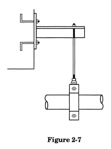
The clamp/pin/rod hardware allows rotation of the pipe, therefore simulating a pinned connection. However, if all spans are of identical length and loading, the reaction of the adjacent pipe span prevents rotation at the support, therefore simulating a fixed connection. The true condition is somewhere in between, so a compromise approximation is reached:

with the location of the maximum moment being somewhere between the ends and the center (i.e., anywhere) on the span.
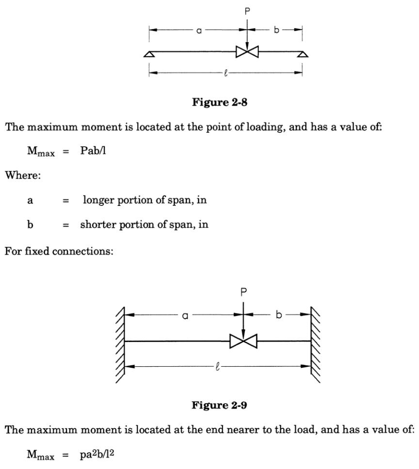
Of course, there sometimes are concentrated loads (valves, flanges, etc.) in the piping system. The effect of these on the pipe stresses can be estimated as well. For pinned connections:
Read More:
To get our piping stress analysis services, please contact our piping engineering firm for a free quote.
