3.3.2 Evaluation of Expansion Joint Allowable Movements
- Meena Rezkallah, P.Eng.
- Jul 11, 2020
- 2 min read
Updated: Dec 20, 2020
Since the failure mode of expansion joints is fatigue, the relative expansion displacements between the start and end of the expansion joint must be checked against the manufacturer's allowables. Note that the allowables provided will not be absolute values, but will be based upon a specific number of cyclic applications. The manufacturer must always provide a fatigue curve or some other type of adjustment factor in order to determine the allowable displacement for a different number of cycles.
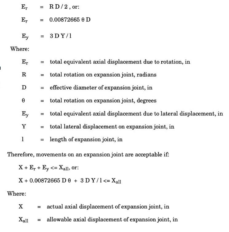
Occasionally, the manufacturer provides allowable movements only for axial displacements. In this case, the equations given in Section 3.3.1 can be used to calculate an equivalent axial displacement from lateral and rotational displacements:

Example: Assume that the expansion joint used in the example from Section 3.3.1 must be checked for its range of applied expansion displacements. The following parameters apply:
Number of Convolutions = 12
Manufacturer's allowable axial displacement (for 3000 load cycles) = 1.43 in
The expansion joint runs between node points 120 and 125, with the axis of the bellows coincident with the global X-axis, in the stress analysis model. The range of expansion displacements (assume that fewer than 3000 cycles are expected) from the stress analysis output are shown below:

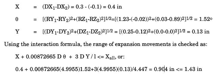
Now it is necessary to compute the relative displacements between the ends of the expansion joint. This is often not a simple task since the rotations of the expansion joint ends can cause lateral translations which don't produce axial deformation of the joint. In the event that displacements and rotations are small, and the expansion joint runs along a global axis, the relative displacements of the expansion joint can be fairly closely approximated:

Read More:
For more info about our engineering services specially our piping stress analysis, please contact us and our pipe stress engineers will help you.
