
ASME B31.3 Pressure Design of Welded Branch Connections
- Meena Rezkallah, P.Eng.
- Jul 29, 2017
- 3 min read

The pressure design of branch connections is based on a rather simple approach, although the resulting design calculations are the most complex of the design-by-formula approaches for pressure design provided in the Code. A branch connection cuts a hole in the run pipe. The metal removed is no longer available to carry the forces due to internal pressure. An area replacement concept is used for those branch connections that do not either comply with listed standards or with certain designs (see Section 4.7). The area of metal removed by cutting the hole, to the extent that it was required for internal pressure, must be replaced by extra metal in a region around the branch connection. This region is within the limits of reinforcement, defined later.
The simplified design approach is limited with respect to the geometries to which it is considered applicable. These limitations are as follows:
The run pipe diameter-to-thickness ratio is less than 100.
The branch-to-run diameter ratio is not greater than one.
The angle B (angle between branch and run pipe axes) is at least 45°.
The axis of the branch intersects the axis of the run pipe.
Where the above limitations arc not satisfied, the designer is referred to para. 304.7.2 (see Section 4.15). Alternatives in that paragraph include proof testing and finite-element analysis. Paragraph 304.3.5(e) suggests consideration of integral reinforcement or complete encirclement reinforcement for such branch connections.
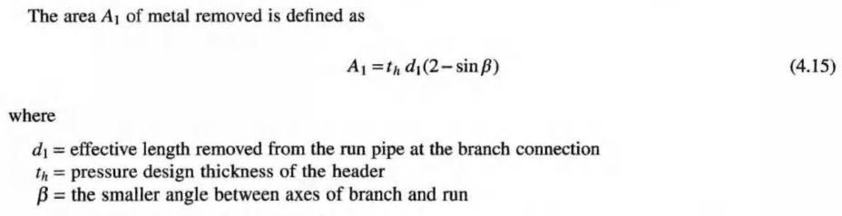
For a 90 deg. branch connection, d1 is effectively, the largest possible inside diameter of the branch pipe; the inside diameter of the pipe if fully corroded and with the full mill tolerance removed from the inside of the pipe.
Figure 4.7 illustrates the nomenclature and process.
The angle B is used in the evaluation because a lateral connection, a branch connection with a P other than 90°, creates a larger hole in the run pipe. This larger hole must be considered in d1. For a lateral, d1 is the branch pipe inside diameter, considering mill tolerance and corrosion/erosion allowance, divided by sin B. The (2 — sin B) term is used to provide additional reinforcement that is considered to be appropriate because of the geometry of the branch connection.
The pressure design thickness is the pressure design thickness of the run pipe, with one exception. If the run pipe is welded and the branch does not intersect the weld, the weld quality factor E and strength reduction factor W should not be used in calculating the wall thickness. The weld quality factor and strength reduction factor only reduce the allowable stress at the location of the weld.
Only the pressure design thickness is used in calculating the required area since only the pressure design thickness is required to resist internal pressure. Corrosion allowance and mill tolerance at the hole are obviously of no consequence.
The area removed, A\, must be replaced by available area around the opening. This area is available from excess wall thickness that may be available in the branch and run pipes as well as added reinforcement, and the fillet welds that attach the added reinforcement. This metal must be relatively close to the opening of the run pipe to reinforce it. Thus, the metal must be within a certain limited area in order to be considered appropriate reinforcement of the opening.
The limit of reinforcement along the run pipe, taken as a dimension from the centerline of the branch pipe where it intersects the run pipe wall, is d2, defined by

The area A4 is the area of properly attached reinforcement and the welds that are within the limits of reinforcement. The Code specifies minimum weld sizes in para. 328.5.4. The designer is directed to assume that the minimum dimensions specified by the Code arc provided, unless the welder is specifically directed to make larger welds. The ASME B31.3 Code does not require the designer to specify branch connection weld size, because generally acceptable minimum sizes are specified by the Code. Additionally, the ASME B31.3 Code differs from the Pressure Vessel Code in that strength calculations for load paths through the weld joints are not required. #Little_PEng.
Engineering Consultant Services