The typical project evolution can generally be divided into three principal stages. The first stage comprises inception, assignment of responsibilities, preliminary design, and estimating. The second stage comprises detailed design, procurement,and definitive cost estimating. (Depending on the project schedule, production of hardware, site preparations, and construction may also be initiated at this stage.) The third stage comprises completion of engineering, production of equipment,erection, start-up, and commercial operation of the systems. Although the demarcation between the various stages may vary with the organization performing the work,the concept remains unchanged. The following discussion describes the various documents that are normally prepared in each phase of the project.
First Stage
Contract Specifications Contract specifications are normally prepared under the sponsorship of the owner to define the owner’s basic requirements of the piping system(s). The contract specification establishes the applicable codes and standards, the owner’s requirements, and the obligations of the parties involved in the project. It is expected that the organization charged with the development of the design will develop all design data (to the satisfaction of the owner) not expressly provided by the owner in the contract specification.
Codes and Standards Although codes and standards are not prepared by any of the parties involved in a project, they are discussed here because of their importance. New or retrofit construction of almost every type of facility is usually regulated by a government agency at the federal, state, and/or local level. Regulators establish safety standards for the purpose of protecting workers and the general public. The regulators may directly issue these regulations or they may invoke industry standards by reference. Furthermore, in locales where no laws exist to regulate safety standards, the owner (as advised by the underwriter) may mandate compliance with certain national construction codes or standards. Also, the piping industry regulates the safety of its projects by establishing minimum design requirements. Therefore,prior to proceeding with the design, the design engineer must establish what the regulatory requirements are. For a detailed discussion of codes and standards, refer to previous post "Piping Codes and Standards".
Because codes and standards have a significant impact on the project, it is paramount that the codes and standard to which the project must conform be established in the early stages of the project, preferably in the contract specification.
Design Criteria Before the detailed design is begun, it is usually advantageous for the project to prepare a comprehensive set of documents defining the system design criteria. This criterion may be part of overall project design criteria or may be a separate document prepared solely for the piping design. In either case, the design criteria should reiterate the design requirements delineated in the contract specification and should define the applicable codes and standards, environmental conditions, design parameters, and other pertinent design bases that will govern the work. The design criteria can be updated as the design progresses to reflect any change in the design basis.
Calculations Calculations are documents prepared to support the establishment of flow rates, system pressures, temperatures, pipe and vessel wall thickness, heat transfer rates, and other design parameters. Calculations are also prepared for the pipe stress and flexibility analysis and pipe support design.
Because calculations form the foundations for the piping system design, their quality is paramount. The documents used for procurement, construction, and licensing must be supported by suitable calculations. Because the design process is an iterative process, it is usual practice to issue calculations at various stages of completeness, based on firmness of the design input. The intended use of the calculation must be commensurate with the reliability of the results. Calculations may be issued as ‘‘preliminary status’’ for in-house review, estimating, and bidding. Unless project conditions dictate otherwise, award of contracts, fabrication, and erection should be based only on final calculations derived from firm data. If calculations are not firm, precautions must be taken to minimize the impact of any changes resulting from changes in the calculation results.
System Descriptions The many organizations engaged in piping system design may vary the format and content of system descriptions (SDs) from that described here based on their needs. Systems whose operation may have public safety implications (e.g., nuclear power plant systems and chemical plant systems) may require very detailed system descriptions. The purpose of the system description is to set forth, specifically in writing, the functions, intent of the design, and major features of the system. Since some systems need mechanical, electrical, and control system discipline inputs, each discipline may prepare its own system description, or alternatively, one document containing all discipline criteria may be prepared. Customarily, the mechanical discipline assumes the lead for preparing system descriptions for piping systems. The four major topics covered in a typical SD are
(1) system design bases,
(2) operating modes(start-up, normal, shutdown, emergency, or as appropriate),
(3) descriptions and performance ratings of major equipment, and
(4) control concepts.
The design basis stated in the SD is used to develop the system flow diagram(which shows the features necessary to accomplish the design basis) and the piping and instrumentation diagram (which shows the basic controls, interlocks, pipes,valves, vessels, pumps, and miscellaneous equipment comprising the system). There-fore, the system description is important in the development of the documents used in procurement, manufacturing, fabrication, and erection.
Table B1.1 presents topics to be covered in a system description applicable to fossil fuel and nuclear power plants. Systems for other uses may not require all the topics listed or may require topics not covered in the table. In any event, the SD should include no more and no less than what is required to fulfill the purpose stated above. In this example, no more information is presented than is necessary to obtain the construction and operating permits from the government authorities and to provide direction to the users of the document (designers, engineers, opera-tors, vendors, etc.).

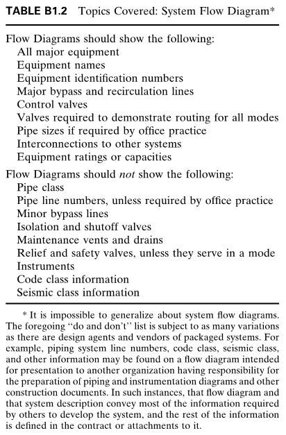
System Flow Diagram The system flow diagram (SFD) serves to illustrate the system description. To realize full benefit from the SFD, it should be issued with the SD. The SFD extends the purpose stated for the system description by schematically showing the operational relationships among the major system components and by stating the design and expected process variables for selected modes of operation. Table B1.2 presents a list of topics to be included and excluded from the SFD. Figure B1.1 is a portion of a typical system flow diagram based on the concepts described above.

Piping and Instrumentation Diagram The piping and instrument diagram (P&ID) provides a schematic representation of the piping, process control, and instrumentation which shows the functional relationships among the system components. The P&ID also provides important information needed by the constructor and manufacturer to develop the other construction input documents (the isometric drawings or orthographic physical layout drawings). The P&ID provides direct input to the field for the physical design and installation of field-run piping. For clarity, it is usual practice to use the same general layout of flow paths on the P&ID as used on the system flow diagram.
The P&ID ties together the system description, the system flow diagram, the electric control schematic, and the control logic diagram. It accomplishes this by showing all the piping, equipment, principal instruments, instrument loops, and control interlocks. The P&ID contains a mini-mum amount of text in the form of notes (the system descriptions minimize the need for text on the P&ID). The first P&ID in the set for the job should contain a legend defining all symbols used; if certain symbols are defined elsewhere, it maybe appropriate to only reference their source. The P&IDs are also used by the start-up organizations for preparing flushing, testing, and blowout procedures for the piping system and by the plant operators to operate the system. The correctness and completeness of the SD, SFD, and P&ID drawings are crucial to the success of the start-up program.
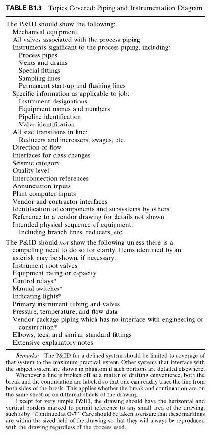
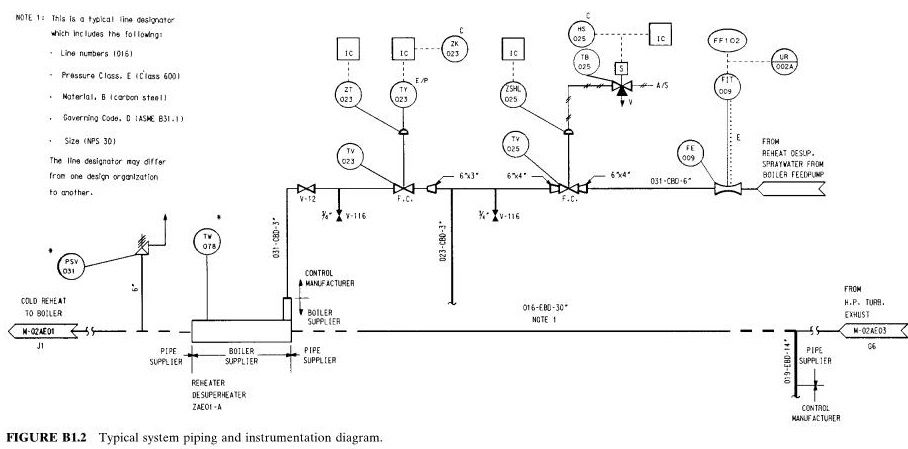
Table B1.3 presents statements of what is included and what is not included in the P&ID. Figure B1.2 depicts a portion of a typical P&ID that complies with the intent of ISA-S5.1, Instrument Symbols and Identification, and with recent electric utility standard practice.

Piping Physical Sketches and Composite Drawings Isometric or orthographic piping sketches are made, initially of the large-bore piping and later of the small-bore piping, as determined by project requirements. Portions of other piping systems, and structural, electrical, control, and HVAC information may be included in these sketches (in which case they are called composite drawings). These piping drawings form the basis for the working physical drawings such as the system isometrics. The sketches and composites are not used for construction or manufacture; they represent the precomputer version of the present database in a computer-aided design (CAD) system, or one of its several derivative systems, which can provide the design study more efficiently than manual methods in many instances today. Computer-aided design and drafting (CADD) software packages are available from a number of commercial sources.
Composite drawings are used to clarify functional relationships among significant elements of various systems. Figure C10.1 is typical of a composite that might be found in an operating manual or hazards study.


Second Stage
With the completion of the initial draft of the calculations and P&ID, the piping design progresses to the second stage, which consists of the detailed physical design of the piping system, piping stress analysis, and procurement of materials. The types of documents typically issued during this phase are purchase specifications, design specifications, piping erection specifications, piping orthographic drawings, piping isometric drawings, fabrication details, and equipment lists.
Design Specifications Design specifications are prepared to define the performance requirements for services and materials. The design specifications may be prepared for in-house design work to control the quality of work performed, or the specification may be issued to govern contracted products and services.
For nuclear power plant systems and components required to meet ASME Section III Code requirements, the design specification takes on added importance. A requirement of the ASME Section III Code is that a Design Specification be prepared to provide a complete basis for ASME Section III Division 1 Construction. As a minimum, the ASME Design Specification must define the boundaries of the item covered, the design requirements, environmental conditions, ASME Code Classification, material requirements, operating requirements, effective Edition, Addenda, and Code cases used for construction. Design specifications can stand by themselves, or they can consist of a cover specification incorporating, by reference, all the design documents required to perform the work.
Procurement Specifications The procurement specification for piping fabrication should define the scope of work, applicable codes and standards, environmental conditions, material requirements, fabrication and examination requirements, testing requirements, and documentation requirements. The specification should reference the applicable design documents (e.g., piping isometric drawings) which govern the work. These documents should be made available to the supplier.
Erection Specification The specification for piping erection should specify the applicable codes and standards governing the work. The specification should also delineate any fabrication,quality, examination, testing, and documentation requirements imposed beyond those required by the code. Also, all design and fabrication documents should be incorporated into the erection specification.
Physical Design Drawings General practice among engineering organizations is to prepare orthographic piping drawings. With the development of three-dimensional computer-aided design (3D CAD) software, the designer can check for interference and can generate different views. Once the orthographic drawings are completed, they may be issued for piping fabrication and construction. However, for complex piping systems, it is common practice to develop separate piping isometric drawings for each pipe run. For pipe stress analysis, fabrication, and installation, the piping isometric drawings are easier to use than the orthographic drawings because all the information on the isometric drawing pertains to the piping of interest—the drawing is not cluttered with extraneous information. Also, the isometric drawing is more easily visualized. Figure B1.3 depicts a typical isometric drawing. Whether the scope of the project dictates that piping spools be shop-fabricated or field-fabricated, isometric drawings are indispensable in relaying the pipe fabrication requirements of the craft.

Stress Analyses Piping stress analyses is a term applied to calculations which address the static and dynamic loading resulting from the effects of gravity, temperature changes, internal and external pressures, changes in fluid flow rate, seismic activity, fire, and other environmental conditions. Codes and standards establish the minimum scope of stress analysis. Some codes prescribe loading combinations with not-to-exceed stress limits.
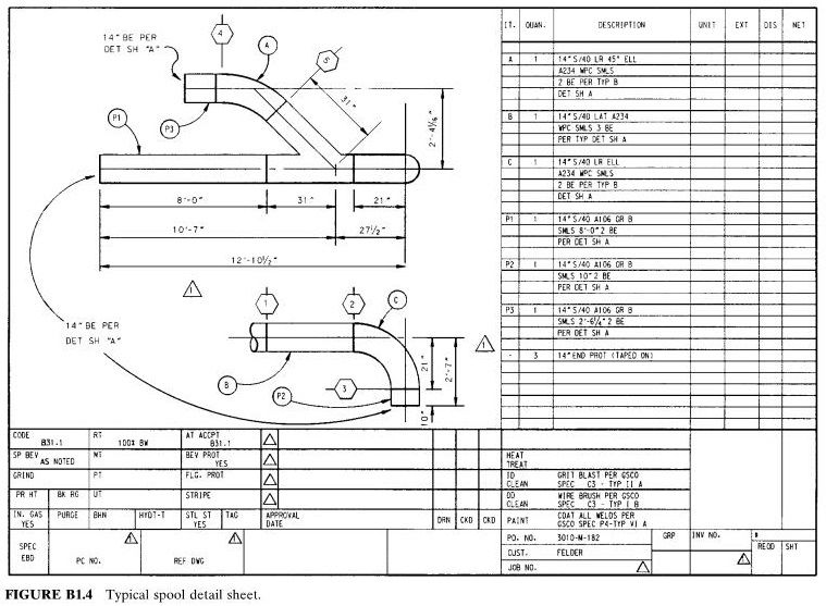
Piping Spool Drawings The piping spool drawing (also referred to as a spool sheet) is the shop detail drawing developed by the pipe fabricator from the piping isometric, or the piping orthographic, for each prefabricated section of piping. Generally, a spool sheet covers only one spool, whether the spool consists of only one fitting or of many piping elements (limited in size only by shipping or handling capabilities). The spool sheet should specify all dimensions, materials, fabrication procedures, examination and testing requirements, and code stamping requirements, as applicable.The spool sheet may also be used to document the performance of the required operations. Figure B1.4 is an illustration of a typical spool sheet. It is customary for the engineering organization to review the spool sheets to ensure that the fabricator properly interprets the code, specification, and design documents.

Equipment Drawings The equipment supplier generally submits certified equipment drawings to the engineer. These drawings may be subject to approval by the engineer to ensure that the specification requirements are met. Also, the drawings are used to finalize the facility design; i.e., the physical and operating characteristics of the actual procured equipment are incorporated into the design.
The supplier document should, as a minimum, contain the following information:
1. Component outline dimensions 2. Location and size of service connections 3. Bill of materials 4. Service requirements 5. Maintenance procedures 6. Instruction manual and list of recommended spare parts 7. Diagrams for piping, logic, electrical wiring, and instrumentation
Pipe Support Drawings The design and procurement of pipe supports are usually accomplished in one of the following ways. The supports can be pre-engineered by the engineer, or the design can be contracted to a pipe support manufacturer. In the first case, the engineer prepares a detailed pipe support drawing containing the necessary fabrication details and bill of materials. The pipe support fabricator needs only to fabricate the support in accordance with the drawing. In the second case, the engineer specifies the direction of restraint, the type of support (e.g., variable, constant, rigid), and the support load. The support manufacturer prepares detailed shop fabrication drawings for shop use. The support drawings should contain the same level of detail as described for spool sheets. As with spool sheets, the engineer reviews the pipe support drawings for compliance with the purchase specification.
Third stage
As the piping system design reaches completion and materials begin to arrive at the job site, the project enters the third stage. It begins with the installation of the piping system.
During installation of the piping system, it is imperative that deviations from the design precipitated by variations in field conditions be controlled and reconciled by engineering. For this purpose, engineers and constructors have developed several vehicles by which deviations are identified and resolved. The following sections describe some of these vehicles. The titles of these documents may vary from organization to organization; however, their purpose remains the same.
Supplier’s Deviation Disposition Request If a supplier cannot furnish material conforming to the purchase specifications, the supplier may request a design change by completing a Supplier’s Deviation Disposition Request (SDDR) form. The request should identify the existing condition, the reason for the change, the technical justification, and the proposed alternative. Engineering can expeditiously evaluate the condition and prepare a reply on the same form if no review of supplier stress analysis calculations, new laboratory test results, or any other significant procedure is required. In some cases the SDDR would be resolved after a reiteration of design and testing submittals, and approvals, as for an original design.
Field Change Request If a contractor cannot install an item as shown on the design documents (or if the contractor identifies an advantageous alternative to the design), the contractor may request a design change by completing a Field Change Request (FCR) form. The request should identify the existing condition, the reason for the change, and the proposed alternative. Engineering can expeditiously evaluate the condition and prepare a reply, often on the same form. For an FCR that involves significant technical problems, the closeout might be conditioned on test results, etc., as described for the SDDR.
Nonconformance Report When an installation does not conform to the design document, a non-conformance report should be generated to document the discrepancy. The report is submitted to the engineer for evaluation and disposition. The engineer determines whether the condition still satisfies the functional requirements of the original design and either approves the FCR or initiates further action. If the deviation cannot be accepted, the engineer will require that the nonconforming item be repaired or replaced to meet the original design requirement.
Start-up Field Report As each system installation is completed, the contractor turns the system over to the start-up group for system checkout and performance testing. Any deficiencies encountered by start-up are documented on Start-up Field Reports that are submit-ted to the engineer for resolution. The report should describe the deficiency and should, if possible, offer a recommendation for corrective action.
Conclusion The careful and timely preparation of design documents is crucial to the economical and successful installation of a piping system. When prepared in the proper sequence, the engineering documents build on the information developed in the foregoing documents, allowing for an organized and methodical development of the project. Thus the number of iterations in the design process is minimized, and schedule and costs are controlled. For additional information on some of the topics in this post, see other posts under these headings: CAD, computer-aided design,computer-aided drafting, and computer programs.

