3.4.3.2 Modeling Nozzles for Flexibility Calculations in CAESAR II
- Meena Rezkallah, P.Eng.
- Aug 26, 2020
- 4 min read
Updated: Dec 20, 2020
Nozzle flexibilities are most often modeled by describing two separate entities — the piping system and the vessel, and then connecting them with the zero-length WRC 297 flexibility element. Therefore there will be two node points at the exact same location in the space — the node representing the surface of the vessel, and the node representing the end of the pipe. This usually means using a rigid element to represent the radius of the vessel.
Various examples of how to model nozzle to vessel connections are shown in Figures 3-88, 3-89, and 3-90.
Figure 3-88 represents the simplest model. In this case, there are no thermal movements imposed from the vessel, and the overall stiffness of thevessel is insignificant when compared to the localized flexibility. Accordingly, the vessel proper is not modeled, but is represented by an anchor with the WRC 297 stiffnesses.

In this model, the user defines a vessel flexibility at node point 5 (with no vessel node point defined). This causes CAESAR II to insert a flexibility element between node point 5 and an infinitely rigid point in space (effectively a flexible anchor). Element 5 to 10 is defined as a normal pipe element. Note: The user should not put any anchors, restraints or non zero displacements at any WRC 297 nozzle or vessel nodes. CAESAR II inserts all the necessary restraints and/or anchors into the model to define the nozzle/vessel connection (i.e., 3 translational restraints and 3 rotational restraints).
A more complex model is shown in Figure 3-89. In this case the radius of the vessel is modeled as a weightless rigid element. This incorporates the effect of the radial expansion of the vessel on the piping system; also, other thermal expansion of the vessel may be entered as imposed displacements at node point 5. This model, as does the previous one, still assumes that the overall stiffness of the vessel is insignificant when compared to the localized flexibility.

In this model, element 5 to 10 is coded as a weightless rigid, with the length equal to the outer radius of the vessel, and the material and temperature that of the vessel. Thermal growth at the centerline of the vessel at the elevation of the nozzle is calculated and imposed at node point 5. A nozzle is defined at node point 15, with a vessel node of 10, so a WRC 297 flexibility element is automatically inserted between these two nodes. Element 15 to 20 is defined as a normal pipe element.
An even more complex model is shown in Figure 3-90. In this case the entire vessel is modeled using pipe and weightless rigid elements, and anchored at its base. This automatically incorporates the effect of all thermal expansion of the vessel, as well as its overall stiffness, on the piping system.

In this model, the vessel is built of three pipe elements going from node point 5 to 20. The diameter, thickness, material, and temperature of the elements are the same of those of the portion of the vessel which they represent (for example, element 5 to 10 may represent an ambient skirt). An anchor is coded at node point 5 to represent the base anchorage of the vessel. Element 15 to 25 is a weightless rigid, with the length equal to the outer radius of the vessel, and the material and temperature that of the vessel — this provides the radial growth of the vessel. A nozzle is defined at node point 30, with a vessel node of 25, so a WRC 297 flexibility element is inserted here. Element 30 to 35 is entered as a normal pipe element.
Flexibilities of configurations not explicitly covered by WRC 297 may be approximated using the bulletin—the results, although not completely accurate, will probably be more accurate than using rigid connections. For example, using WRC 297 for a pipe attachment to the head of a vessel may yield adequate results when choosing values of D, L1, or L2 as shown in Figure 3-91. Because this is an extension of the WRC 297 application, the user may wish to perform a sensitivity study of the effects of selecting different values of these dimensions.

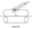
In the event that the nozzle is not normal to the vessel surface, WRC 297 may still give reasonable results. For example, one means of modeling a hillside nozzle is shown in Figure 3-92. Element 30 to 35 should be modeled as a weightless rigid, with a length equal to the outer radius of the vessel, and the outer diameter, wall thickness, material, and temperature equal to those of the vessel. WRC 297 flexibilities are calculated and inserted between node points 35 and 40. Element 40 to 45 is a 1/4" long pipe element (with the same properties of the nozzle) extending along the same line as element 30 to 35. Element 45 to 50 is the pipe nozzle connection itself. Note: The idea of the 1/4" long nozzle element is to properly orient the local vessel flexibilities with respect to the axial, longitudinal and transverse vessel directions.

This same idea can be used to model a lateral branch connection, as shown in Figure 3-93. In this case, the WRC 297 flexibilities are inserted between node points 110 and 115, and element 115 to 120 is the 1/4" long element used to orient the local axes.

Read More:
Located in Calgary Alberta, We offer our Piping Engineering Services, Skid Design Services and Structural Engineering Services across Canada. To get our Piping Stress Analysis Services, please contact our Engineering company.
Our professional piping stress engineers have a bachelor's and Masters degree in mechanical / structural engineering and province licence (P.Eng.) in Alberta, Saskatchewan, British Columbia and Ontario. We review, validate, certify and stamp piping and structural packages.
